Tuesday, April 26, 2016

SHELL . MAKING

FINAL PIECE . TWO


 This is the selected section on the reference model.


*****


*****


SHELL . MAKING

FINAL PIECE . ONE


This is the selected section on the reference model. 


*****


*****


SHELL . MAKING

FIRST ATTEMPT - TRIAL


This is my first attempt at bashing aluminium, trying to explore the surface of the shell and test out different ways of bending the aluminium by bashing it against different surfaces. The most difficult thing that I have realised via this attempt was the complexity and subtlety of this organic shape. None of curves on the surface only falls in one way.  Often when I curve the aluminium in one direction and then try to stretch it in the other direction, the shape ended up working against each other. It was very hard to achieve a level of accuracy of with such a big working surface. Hence, as Russell suggested that I should do little pieces of just a part of the reference model and do it to a lot of detail. Note how the aluminium was stretched out too far and broke at the middle due to over-bashing.

SHELL . MAKING

@Metal Workshop
19 April 2016


I started exploring the entire surface of the reference model on a large piece of aluminium, attempting to understand the art of hammering and the nature of aluminium and the techniques of bending the metal. 

SHELL . REFERENCE MODEL 


This is the reference model put together after being laser cut. The model seemed to work fine even though123D Make has highlighted many pieces in red. The only issues was that it did not joint too well in the centre of model. 
SHELL . 123D MAKE
SECOND ATTEMPT 


Doing 36 panels of laser cutting is a waste of time, and Russell suggested that I should try 'Interlocked Slices' instead. Last time when I tried laser cutting, I have exploded the model to double its original size. I realised it was too big after I have laser cut it out and this time I reduced the scale down by 15%.


 I spent a lot of time changing around the slice directions and this was the best I could get, there were still some pieces highlighted in red by 123D Make indicating either there was a weak point in the slices or it does not join properly with the adjacent pieces. 'Interlocking Slices' does not like organic shapes such as this part of the shell but I had to go with this best result.  


This was the final laser cutting template edited in Adobe Illustrator ready to go.
SHELL . LASER CUT
FIRST ATTEMPT 
7 APRIL 2016


I generated a pdf. file from 123D Make and bought it with me to the FabLab. This is first page of the pdf. as it shows the shape outlines in blue and the engravings in red. 


I have never tried laser cutting, so I asked Anthony for help and he told me that the maximum working surface for laser cutting is 300x600 mm and the outlines should be in red RGB colour, and the engraving should be in blue at 0.001pt. I had to then edit the first template in Abode Illustrator and laser cut it to see if it works out well. 


Once the template is edited in Adobe Illustrator, the file is transferred to a laser cutting software. Anthony advised that I should try it on 2mm screen board to see if it works. 


The first template turned out fine. However the only issue was that I needed to laser cut at least another 36 panel.

SHELL . 123D MAKE 
FIRST ATTEMPT


After I have chosen the part of the shell that I am interested in, I went back to 123D Catch and trimmed the section, and then transferred it back to 123D Make again. I initially thought about doing the template model in stacked slices, as it seems to be the most accurate way of presenting this complex and organic shape. 


I played around with 'Slice Direction' tool in 123D Make and this seemed to be the best angle where none of the pieces are highlighted as red by the software. It indicates that all the templates should work for laser cutting and the model will be put together in a logical way. 


However, I ended up with 76 A4 sheets from the template and there were 198 pieces needed to be laser cut. 
SHELL . SELECTED AREA


Initially, I was thinking to model the entire shell. However, when I transferred the entire model from 123D Catch to 123D Make, 123D Make refused to generate a template due to the complexity of the geometry. I got some advices from Alex that I could potentially go to the 'Modify Form' tab in 123D Catch and change the 'Shrinkwrap' percentage to reduce the geometry of the shape and hence generate a template. In fact, I have tried to bring the shrinkwrap percentage to as close to minimum as possible, it still didn't work on the software and the shape turned out very inaccurately. As a result, I decided that I should just focus on one part of the shell and this is the section that I have selected. This section is chosen due to my personal interest in the shape and the workability of the shape both in the act of physical making and laser cutting. 

Sunday, April 24, 2016

SHELL . ARCHITECTURE

SHELL - Golden Ratio 

The Golden Ratio - Michal Urbanski:

The Golden Ratio or the Fibonacci Numbers, 0.142857 (1/7), is a significant ratio which dominates the human perception of the universe and the aesthetics in the field of Astronomy, Mathematics, Architecture and Fine Arts for thousands of years. 'The Golden Curve' generated by the Golden Ratio grid happens to match with many curves found in the nature. The Nautilus Shell is one. Of course not all the shape of the Nautilus shells match with the Golden Ratio Curve, however it is often possible to find one that matches exactly. Looking back to history, many pieces of architecture were designed on the basis of the Golden Ratio.Often, the Golden Ratio was applied to both the layout of the building as well as its façades. Examples are the Great Pyramids built by the Egyptians, the Parthenon  built from 447 - 438 BC, the Villa Rotonda by Palladio, the Notre Dame in Paris and many buildings by Le Cobusier  such as the Villa Savoye and many more. For architects, the Golden Ratio is a key to achieve a sense of compositional beauty in a logical and orderly manner. It imposes a sense 'decorum' upon the beholders. 


SHELL - 'Objects of Poetic Reaction'


Le Corbusier had a collection of natural found objects in his studio, this is what he called 'objets à réaction poètique'  , 'objects of poetic reaction'. These objects include pine-cones, bones, natural stones, crab shells and the Nautilus shells. For Le Corbusier, a shell is a source of both structural and aesthetic inspiration for his creation of Architecture. Le Corbusier believed that an architectural form inspired by nature will create a sense of harmony with its surrounding site which belongs to nature.


Some theories argue that Le Corbusier's Ronchamp was inspired by the shape of a crab shell. Simultaneously, his staircase design in the Villa Savoye came from the internal structure of a shell.  


SHELL - Architectural Motif

blue spiral staircase Eric Dufour: X-ray Nautilus shell by Bert Myers.    Via LUSHLIGHT. (iainclaridge.net):

The 'Shell' has became an architectural motif throughout history. Shell, the object, was once the money for many ancient civilisation; it appeared in faire tales and Greek mythologies.  Because it has both social, historical and cultural significance to the human beings, it is used as an occurring feature in architecture. This often appears in the ornament, material finishes, furniture and the structure of a building.  


References 

http://www.furniturelibrary.com/the-sea-shell-design-motif/
http://hyperallergic.com/75809/le-corbusiers-objects-of-poetic-reaction/
 https://www.artsy.net/artwork/le-corbusier-bark-and-shell
https://www.youtube.com/watch?v=ykVBV07fO0I
http://www.goldennumber.net/nautilus-spiral-golden-ratio/ 

Wednesday, April 20, 2016

COMPUTER MODEL . 123D CATCH


This is the model generated by 123D Catch. When the shell was captured, it worked very well on the software, 123D Catch was able to identify all the little details on the shell and represent it in a highly accurate way. When the shell was captured, part of the table underneath the shell appeared in the model too. I was able to trim the table off using the selection tool in 123D Catch. 

Tuesday, April 5, 2016


 STAGE ONE

GENERATE 3D MODEL FROM PHOTOGRAPH
USING 123D CATCH 


STEP 1: Download 123D Catch from your iphone
appstore


STEP 2: Open the app, sign in using Facebook or 
your own Autodesk account. Press '+' on the up 
right hand corner and press '+' again on the up 
left hand corner to start taking photos of your object. 


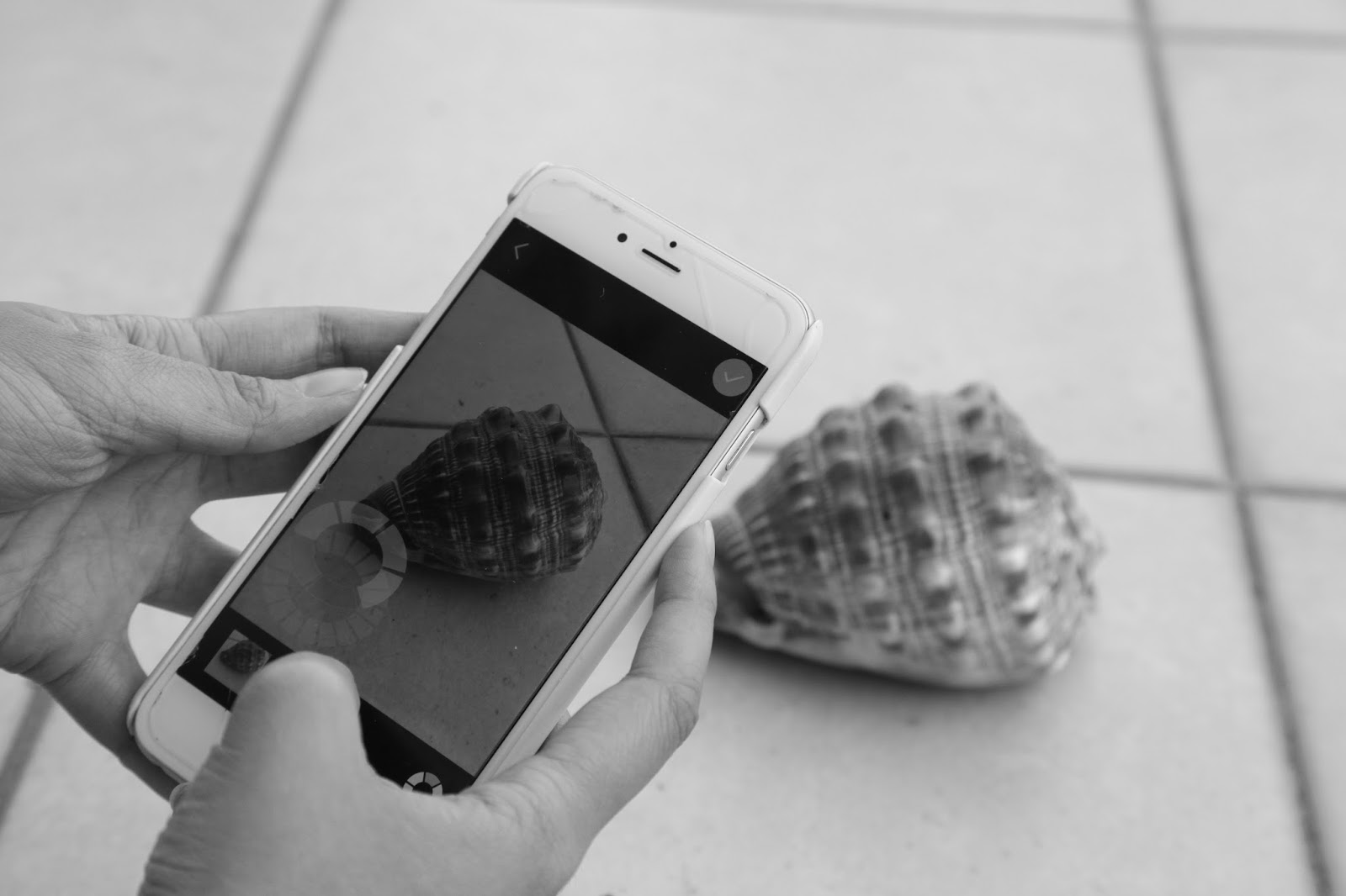
STEP 3: Place your object on a flat plane in a 
simple setting, take photos of it from all different
 angles. 


TIPS: 
1. DO NOT move your object during the 
photographing process. 
2. Take as many photos as you can, normally
30-50 photos are quite ideal to generate a good 
model. 
3. Try to have a clean background when you are
taking the photos, it will make the software easier
and faster to generate your model. 


STEP 4: Once you have finished photographing the
shell from all angles, press the 'tick' button on the
top right hand corner. This will bring you to the 
photo confirmation page. You may delete or add 
some more photos on this page before the model is 
generated. If you feel happy with all the photos 
you have just taken, then press 'submit' button on the
top right hand corner of the page. A black menu will
pop up showing the model generation process. Note
if you have taken heaps of photos, this process might
take hours. Make sure you have a good internet connection
and your phone is always on. 


STEP 5: Once the model is generated, you can 
review it on your phone. 123D Catch will ask 
you whether you want to save this capture and 
you can save it as either 'public capture' or 'private
capture'. You can then tab into the model, 
rotate it around and enlarge it to view the details. 
123D Catch likes complex geometries like a shell, 
therefore it should turn out just like the real object.